I mentioned previously I was shocked that the voltage at my heated bed was only 10.5 volts. I realised I had a problem and wanted to get the voltage up. I wanted to approach this from a scientific view point. I measured and entered the voltages into some simulation package I found in the repositories. The idea was to enter the various voltage drops so I could see the areas of potentially high resistance.
10.5V
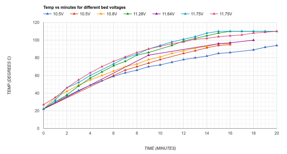
The initial reading at the bed was 10.5 Volts I never got above 100 degrees in fact it took a long time to get from around 80 to 90 degrees. I even tried some cardboard insulation to help the bed heat up more efficiently. When the graph shows to instances of the same voltage the slightly better one is when I tried insulation.
Increased to 10.8V
The first thing I did was to carefully touch the heat sink of my FET and noticed it was cold. Then I checked the voltage at the power supply. It was measured at 12.4 Volts.
I plugged in a Raspberry Pi intended to control the printer. The Raspberry Pi draws 5V with current of 0.5 and 1 A. As the Pi started up, I could hear a difference in speed from my 12V fans. I thought this was odd.
I decided to add more load to the 5 Volt part of the power supply.
The power supply I was using was from a PC. Some older power supplies need a load on the 5 Volts to make the 12 Volts regulate better (never needed this before…). But I measured the bed again and found if the Raspberry Pi was being powered from the 5V then I got 10.8 Volts across my bed.
Increased to 11.28V
I grabbed my Pi LCD screen and connected it as an additional load the voltage increased to 11.28 volts.
Increased to 11.64V
The next thing I did was scratch the solder mask from the copper traces on the RAMPS PCB. specifically the traces of the FET to the connectors. Then I soldered a copper wire over the traces to reduce the resistance of the traces.
Increased to 11.75V
The gauge of cable to the heated bed was 16 AWG I put some wire that was described as 12AWG in parallel with the 16 AWG. The wire would not go into the connector so I put it in parallel for the majority of the distance. I tried to make better solder joints at the heated bed too.
Just to be clear, the actual wire did not have a marking that backed up the gauge so I am a bit sceptical that it truly is 12AWG.
At this point I got to 11.75 Volts. Whist this is still not great the graph shows the time taken to reach 110 degrees is now reasonable. The only improvements left that I can think of is to change the wiring from the power supply to the Ramps board and add a higher load to the 5 Volts of the power supply.
I still do not quite understand why the voltage at the bed has dropped so low. I can only think that the old heated bed had a higher resistance.
